Keysight M3201A/M3202A PXIe Arbitrary Waveform Generators include an embedded Function Generator (FG), Arbitrary Waveform Generator (AWG), and modulator blocks; together, they form a powerful signal generator that is capable of generating standard waveforms (sinusoidal, triangular, square, and DC voltages) or arbitrary waveforms defined by the user and stored on its onboard RAM. With embedded modulator blocks, the output channels can be modulated in phase, frequency, amplitude, or IQ to create analog or digital modulation.
This chapter describes the following topics:
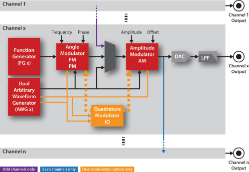
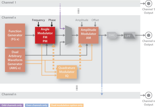
Each channel (Channel 1 to Channel n) has an identical structure that contains a Function Generator (FG), Arbitrary Waveform Generator (AWG), Frequency and Phase Angle Modulator, Amplitude and DC Offset Amplitude Modulator, and an IQ Modulator.
This section describes the following topics:
Compatibility mode, can be changed by open,
is available to support legacy modules and allows the channel numbering (channel enumeration) to start with either
CH0 or CH1.
| Option | Description | Name | Value |
|---|---|---|---|
| Legacy | Channel enumeration starts with CH0 | COMPATIBILITY_LEGACY | 0 |
| Keysight | Channel enumeration starts with CH1 | COMPATIBILITY_KEYSIGHT | 1 |
Legacy modules
refer to SD1 modules that were manufactured by Signadyne before they were acquired by Keysight Technologies.
If the hardware equipment configuration being used only contains modules from Keysight Technologies, channel enumeration should start with CH1.
Each channel has a Function Generator (FG) block that generates basic periodic signals and an Arbitrary Waveform Generator (AWG) block that generates arbitrary waveforms.
| waveShape | Description | Name | Value |
|---|---|---|---|
| HIZ | The output signal is set to HIZ (No output signal is provided.) * |
AOU_HIZ | -1 |
| No Signal | The output signal is set to 0. All other channel settings are maintained. |
AOU_OFF (default) | 0 |
| Sinusoidal | Generated by the Function Generator | AOU_SINUSOIDAL | 1 |
| Triangular | Generated by the Function Generator | AOU_TRIANGULAR | 2 |
| Square | Generated by the Function Generator | AOU_SQUARE | 4 |
| DC Voltage | Generated by the Amplitude Modulator | AOU_DC | 5 |
| Arbitrary Waveform | Generated by the Arbitrary Waveform Generator (See AWG Waveform Types) |
AOU_AWG | 6 |
| Partner Channel | Only for odd channels. It is the output of the previous channel (to create differential signals, etc.) |
AOU_PARTNER | 8 |
* Only available for Keysight M3202A PXIe AWG models
|
Function Name |
Comments |
Details |
|---|---|---|
|
channelWaveShape |
Sets the channel waveshape type |
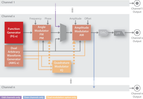
Each channel has a Function Generator (FG) that generates basic periodic signals (sinusoidal, triangular, square, etc.) and is commonly used to generate the RF carrier in modulation schemes. These periodic signals can be modulated in frequency, phase, amplitude, or IQ.
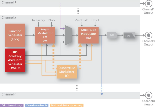
Each channel has an Arbitrary Waveform Generator (AWG) block that generates arbitrary waveforms that can be sent directly to each output channel or they can be used as a modulating signal for the frequency, phase, amplitude, or IQ modulators.
See Working with AWG Waveforms.
Each channel has an Angle Modulator block that has a frequency and phase control.
In angle modulation schemes, these controls set the frequency and phase of the carrier. See Frequency and Phase Modulation (Angle Modulator Block).
|
Function Name |
Comments |
Details |
|---|---|---|
|
channelFrequency |
Sets the frequency of the FG |
channelFrequency |
| channelPhase | Sets the phase of the FG | channelPhase |
| channelPhaseReset | Resets the accumulated phase | channelPhaseReset |
Each channel has an Amplitude Modulator block that has an amplitude and DC offset control; these controls have a combined range from 1.5 V to –1.5 V.
See Frequency and Phase Modulation (Angle Modulator Block).

|
Function Name |
Comments |
Details |
|---|---|---|
|
channelAmplitude |
Sets the output amplitude |
|
| channelOffset | Sets the output DC offset | channelOffset |
Each channel has an Arbitrary Waveform Generator (AWG) block that generates arbitrary waveforms.
This section describes the following topics:
AWG block operation can be configured with a one-step programming process
or with a step-by-step programming process.
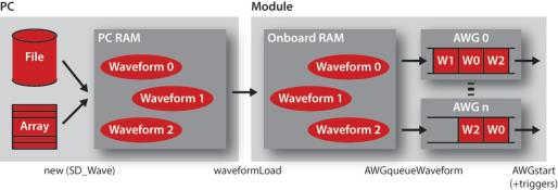
Each AWG block has a flexible waveform queue system that can be used to configure complex generation sequences. In order to generate waveforms, they must be loaded into the module onboard RAM and queued in each corresponding AWG.
The AWG waveform queue system has the following advantages:
Each AWG queued waveform has the following parameters:
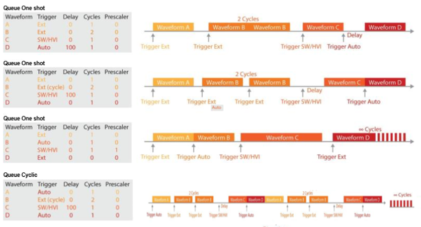
Inter-waveform/inter-cycles discontinuities: The AWG Queue System allows the user to queue many waveforms one after the other. It also provides the capability to set repetition cycles per waveform and repetition cycles for the complete queue. In all these cases, there are absolutely no discontinuities between waveforms or cycles, providing a continuous waveform generation from the last sample point of the finished waveform to the first sample point of the starting waveform.
The user can set a different prescaler value for each of the waveforms queued in the AWG. This prescaler reduces the effective sampling frequency of each individual waveform as follows:
M3201A
0 => fs=500 MS/s
>=1 => fs=100/n MS/s
M3202A
0 => fs=1 GS/s
1 => fs=200 MS/s
>1 => fs=100/n MS/s
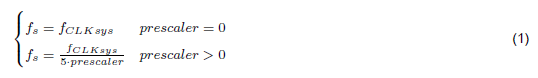
where:
An important advantage of this method is the possibility to change the sampling frequency in real time from one waveform to another, reducing waveform sizes and maximizing the flexibility of the AWG.
A different trigger mode can be configured in each queued waveform.
| Option | Description | Name | Value |
|---|---|---|---|
| Auto | The waveform is launched automatically after AWGstart , or when the previous waveform in the queue finishes | AUTOTRIG | 0 |
| Software / HVI | Software trigger. The AWG is triggered by the AWGtrigger , provided that the AWG is running. AWGtrigger can be executed from the user application (VI) or from an HVI. (See HVI in Keysight M3601A Hard Virtual Instrument (HVI) Design Environment Software .) | SWHVITRIG | 1 |
| Software / HVI (per cycle) | Software trigger. Identical to the previous option, but the trigger is required per each waveform cycle | SWHVITRIG_CYCLE | 5 |
| External Trigger | Hardware trigger. The AWG waits for an external trigger | EXTTRIG | 2 |
| External Trigger (per cycle) | Hardware trigger. Identical to the previous option, but the trigger is required per each waveform cycle | EXTTRIG_CYCLE | 6 |
1 VIHVITRIG is equivalent, but is considered obsolete
Function Name | Comments | Details |
|---|---|---|
AWG | Provides a one-step method to load, queue, and start a single waveform | |
AWGqueueWaveform | Queues a waveform in the specified AWG |
If the queued waveforms are going to use any of the External Trigger modes, the source of this trigger must be configured using AWGtriggerExternalConfig . The available external trigger options.
| Option | Description | Name | Value |
|---|---|---|---|
| External I/O Trigger | The AWG trigger is a TRG connector/line of the module. PXI form factor only: this trigger can be synchronized to CLK10. | TRIG_EXTERNAL | 0 |
| PXI Trigger [0 to n] | PXI form factor only.
The AWG external trigger is a PXI trigger line and it is synchronized to CLK10. | TRIG_PXI + Trigger No. | 4000 + Trigger No. |
| Option | Description | Name | Value |
|---|---|---|---|
| Active High | Trigger is active when it is at level high | TRIG_HIGH | 1 |
| Active Low | Trigger is active when it is at level Low | TRIG_LOW | 2 |
| Rising Edge | Trigger is active on the rising edge | TRIG_RISE | 3 |
| Falling Edge | Trigger is active on the falling edge | TRIG_FALL | 4 |
A different marker can be configured for each AWG channel. All waveforms must already be queued (AWGqueueMarkerConfig ) in one of the module's AWGs.
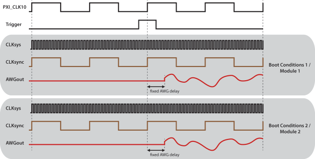
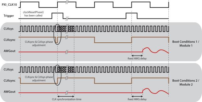
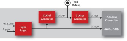
FlexCLK Technology (models w/ variable sampling rate) shows the internal diagram and the operation of the M3201A/M3202A PXIe AWGFlexCLK system. This advanced technology allows you to change the sampling frequency of the AWGs (CLKsys), while maintaining full synchronization capabilities due to the internal CLKsync signal.
CLKsync is an internal signal used to start the AWGs and it is aligned with CLKsys and PXI CLK10. Its frequency depends on the FlexCLK Technology (models w/ variable sampling rate), resulting in the following scenarios:
fCLKsync = fPXI CLK10
When both frequencies coincide, there is no phase uncertainty between both signals and a trigger synchronized with PXI CLK10 will start the AWGs always with the same skew, independently of the clock boot conditions. This ensures proper synchronization between different modules.
fCLKsync! = fP XI CLK10
When both frequencies do not coincide, both signals are still aligned, but there is a phase uncertainty due to their frequency difference. In this case, if a trigger synchronized with PXI CLK10 is sent to the system, there might be a skew between the start of different AWGs.
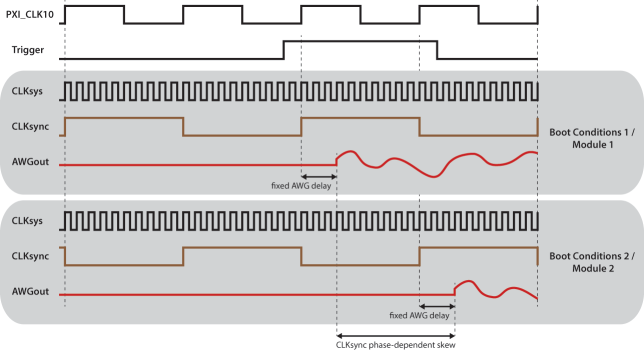
This phase uncertainty can be easily corrected using clockResetPhase . This function sets the modules in a sync mode and the next trigger is used to reset the phase of the CLKsync and CLKsys signals, not to start the AWGs. In this way, the phase uncertainty between different modules or between different boot conditions can be eliminated, resulting in a predictable and repeatable skew.
The two possible sources of waveforms are an array in the PC RAM and a file in the PC HDD. The memory array is just an array of waveform points, without header and without any particular structure. A waveform file is simply a text file with values separated by commas (*.csv).
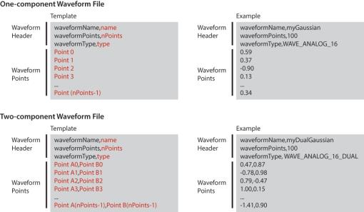
The waveformType is a parameter that tells the module which kind of waveform it used to configure the AWG internally.
See waveformType in waveform file or in new .
Modulation Option |
Description |
Name |
Value |
|---|---|---|---|
| Analog 16 Bits | Analog normalized waveforms (-1 to 1) defined with doubles | WAVE_ANALOG_16 | 0 |
| Analog 32 Bits | Analog normalized waveforms (-1 to 1) defined with doubles | WAVE_ANALOG_32 | 1 |
| Analog 16 Bits Dual | Analog normalized waveforms (-1 to 1) defined with doubles, with two components (A and B) | WAVE_ANALOG_16_DUAL | 4 |
| Analog 32 Bits Dual | Analog normalized waveforms (-1 to 1) defined with doubles, with two components (A and B) | WAVE_ANALOG_32_DUAL | 6 |
| IQ | Analog normalized waveforms (-1 to 1) defined with doubles, with two components (I and Q) | WAVE_IQ | 2 |
| IQ Polar | Analog waveforms (-1 to 1 module, -180 to +180 phase) defined with doubles, with two components (Module and Phase) | WAVE_IQPOLAR | 3 |
| Digital | Digital waveforms defined with integers | WAVE_DIGITAL | 5 |
Signals can be modulated in frequency, phase, amplitude, or IQ.
The output signal of the Function Generator (FG) block or the Arbitrary Waveform Generator (AWG) block can be modulated.
| Option | Description | Name | Value |
|---|---|---|---|
No Modulation | Modulation is disabled | AOU_MOD_OFF (default) | 0 |
Frequency Modulation | AWG is used to modulate the channel frequency | AOU_MOD_FM | 1 |
Frequency Modulation | AWG is used to modulate the channel frequency | AOU_MOD_FM_32b | 1 |
Phase Modulation | AWG is used to modulate the channel phase | AOU_MOD_PM | 2 |
*Models with Option DM1 dual modulation capability (amplitude and angle modulation simultaneously)
The modulating signal is generated using the AWG associated to that particular channel, for example, AWG1 for channel 1. The angle modulator allows the user to create any analog/digital frequency or phase modulation, for example: FM, FSK, PM, PSK, DPSK, etc.

where:
As an example, for the generation of an FM signal with an amplitude of 0.8 Vp, a modulation index (h) equal to 0.5 and a maximum frequency of the modulating signal of 10 MHz, the settings must be A=0.8 and G=5,000,000 (G = h*maxf req[AW G(t)]).

where:
As an example, for the generation of a PM signal with an amplitude of 0.8 Vp and a modulation index (h) equal to 1800, the settings must be A=0.8 and G=180 (G=h).
Function | Comments | Details |
|---|---|---|
modulationAngleConfig | Configures the angle modulator | |
| AWG functions | Control the modulating signal | Signal Generation with the Arbitrary Waveform Generator |
FG functions | Control the carrier signal | Working with Signal Generation/Channel Structure |
The amplitude modulator can be used to modulate the amplitude or change the DC offset of the output signal.
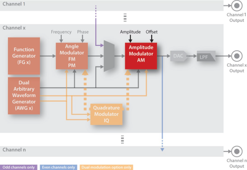
The modulating signal is generated using the AWG associated with a particular channel (for example, AWG1 corresponds to Channel 1). The Amplitude Modulator can be used to create analog/digital amplitude modulation (for example, AM, ASK, etc.).
where:

As an example, for generation of an AM signal with an amplitude of 0.8 Vp and a modulation index (h) equal to 0.5, the settings must be A=0.8 and G=0.32 (G = h ∙A2).

| Function | modulationType (const & value) | Description | |
|---|---|---|---|
No Modulation | AOU MOD OFF | 0 (default) | Modulation is disabled. The channel amplitude and offset are only set by the main registers. |
Amplitude Modulation | AOU MOD AM | 1 | The modulating signal is used to modulate the channel amplitude. |
Offset Modulation | AOU MOD OFFSET | 2 | The modulating signal is used to modulate the channel offset. |
Programming Information
Function | Comments | Details |
|---|---|---|
modulationAmplitudeConfig | Configures the amplitude modulator | |
| AWG functions | Controls the modulating signal | Signal Generation with the Arbitrary Waveform Generator |
| FG functions | Controls the carrier signal | Working with Signal Generation/Channel Structure |
The output signal of the Function Generator can be modulated simultaneously in amplitude and angle (frequency or phase). This allows the creation of an IF signal with amplitude modulation while the frequency is scanned.
However, the most common use of dual modulations is the amplitude and angle modulation decomposed to in-phase (I) and quadrature (Q) components, commonly known as IQ modulation. In order to make the creation of IQ modulations easier, there are dedicated programming functions for that purpose.
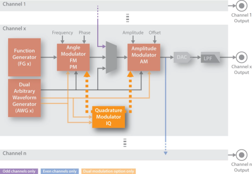
The modulating signals are generated using the IQ Modulation (Quadrature Modulator Block) associated to that particular channel, for example, AWG1 for channel 1. In this case, the waveform loaded into the AWG is composed by the two waveforms (for example, I and Q components, see AWG FlexCLK Synchronization (models with variable sampling rate)).

where:
| Output(t) = A ∙ AWGA(t) ∙ cos(2πfct + ϕc + π/2 ∙ AWGϕ(t)) | (7) |
where:
| A ∙ cos(2πfct + ϕc + ϕ) = A ∙ cos(2πfct + ϕc) cos(ϕ) — A ∙ sin(2πfct + ϕc) sin(ϕ) | (8) |
where the I and Q components are defined as follows:
| I = A ∙ cos(ϕ) | (9) |
| Q = A ∙ sin(ϕ) |
and the IQ components become very useful to set the amplitude (A) and the phase(ϕ) of the output signal, resulting in IQ modulation (or QAM, Quadrature Amplitude Modulation).
| A ∙ cos(2πfct + ϕc + ϕ) = I ∙ cos(2πfct + ϕc) — Q∙ sin(2πfct + ϕc) | (10) |
Function | Comments | Details |
|---|---|---|
modulationIQconfig | Configures the IQ modulation | |
| AWG functions | Control the modulating signal | Signal Generation with the Arbitrary Waveform Generator |
| FG functions | Control the carrier signal | Signal Generation with the Function Generator |
The M3201A/M3202A PXIe AWG has general purpose input/output triggers
(TRG connectors/lines).
A trigger can be used as a general purpose digital IO or as a trigger input, and can be sampled using the options shown below in
Trigger Synchronization/Sampling Options.
| Option | Description | Name | Value |
|---|---|---|---|
| Trigger Output (readable) | TRG operates as a general purpose digital output signal, that can be written by the user software | AOU_TRG_OUT | 0 |
| Trigger Input | TRG operates as a trigger input, or as general purpose digital input signal, that can be read by the user software | AOU_TRG_IN | 1 |
| Option | Description | Name | Value |
|---|---|---|---|
| Non-synchronized mode | The trigger is sampled with an internal 100 MHz clock | SYNC_NONE | 0 |
| Synchronized mode | (PXI form factor only) The trigger is sampled using CLK10 | SYNC_CLK10 | 1 |
The M3201A/M3202A PXIe AWG uses an internally generated high-quality clock (CLKref) which is phase-locked to the chassis clock.
Therefore, this clock is an extremely jitter-cleaned copy of the chassis clock.
This implementation achieves a jitter and phase noise above 100 Hz which is independent of the chassis clock,
depending on it only for the absolute frequency precision and long term stability.
A copy of CLKref is available at the CLK connector.
CLKref is used as a reference to generate CLKsys, the high-frequency clock used to sample data.
Option | Description | Name | Value |
|---|---|---|---|
Disable | The CLK connector is disabled | n/a | 0 (default) |
| CLKref Output | A copy of the reference clock is available at the CLK connector | n/a | 1 |
The sampling frequency of the M3201A/M3202A PXIe AWG (CLKsys frequency) can be changed using the advanced clocking system.
FlexCLK System
where:
The CLKsys frequency can be changed within the range indicated in the datasheet of the corresponding product (clockSetFrequency (Requires Option CLV) ). The CLKsync frequency changes with the CLKsys frequency as follows:

The CLKsync frequency is returned by clockSetFrequency (Requires Option CLV) .
Option | Description | Name | Value |
|---|---|---|---|
Low Jitter Mode | The clock system is set to achieve the lowest jitter, sacrificing tuning speed | CLK_LOW_JITTER | 0 |
Fast Tuning Mode | The clock system is set to achieve the lowest tuning time, sacrificing jitter performance | CLK_FAST_TUNE | 1 |
In M3201A-CLV modules, CLKref frequency (freqCLKref) changes as follows, as a function of CLKsys frequency (freqCLKsys):
In M3202A-CLV modules, CLKref frequecy (freqCLKref) changes as follows, as a function of CLKsys frequency (freqCLKsys):
